November 12, 2025
By: Nicolas Kirkvold
www.utieng.com
Introduction:
In the modern manufacturing world, “Quality” is often determined by factors that one cannot see with the naked eye. Due to the nature of the machines and processes involved, many times these factors are either obscured by the manufacturing process or not visible to the human eye. In our case, the determining mark of quality was both obscured and not visible. Additionally, the traditional method of quality assurance was resulting in a safety issue. The solution we developed was a novel thermal camera application that received high praise from the client and revolutionized their approach to quality control for manufacturing and improved safety.
Background:
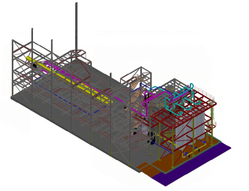
Unified Theory Inc. (UTI) was initially approached by a client to assist in designing safety guarding for a lamination process for a product manufacturing line making something akin to safety stickers. This process saw a flexible sheet of product being laminated to its backing material through the application of hot glue. In this area there was a safety hazard UTI was tasked with designing guarding to protect against. Guarding this location would have been a simple task were it not for the additional complication that the operators had to peel apart the backing material on the edges of the web to “feel” the glues position and ensure the usable section of the web was wide enough for a future process. The edge of the glue was unable to be verified visually by a person and could only be confirmed through tactile inspection (felt by hand) with the operators putting themselves into direct contact with the moving product.
This quality check was crucial to the process and meant that the operators needed access to the location that guarding would limit. As a result, UTI’s attention was shifted toward determining a way to perform the process check remotely. Initial brainstorming exercises came up with a myriad of possible physical tools that could peel apart the unglued edges of the material and check the glues position from the edge. However, these physical checks were deemed insufficient due to either mechanical complexity and the potential of damaging the product.
This left the team constrained to non-invasive inspection methods. Sensors, such as time-of-flight sensors, that determined differences in thickness between the glued and unglued portions proved unreliable as the material the flexible sheet was made of was unpredictably uneven and the old machine this process ran on produced enough vibration to further skew results. Visual inspection proved difficult, even with high-res imaging, as the backing material that faced outward was opaque. Adding a bright back light did fix the opacity but the uneven material of the product meant that the glues edge was difficult to distinguish.
Method:
Finally, the brainstorming team concluded that a Thermal/IR camera could potentially be used. Thanks to the residual heat of the hot application process, the glue was still warm at the location to be inspected. Additionally, the poor heat conductivity of the backing material as well as the thickness and heat capacity of it relative to the glue, meant the backing material stayed cool by absorbing little heat and losing what heat it did gain to the surrounding air quickly. As a result, the UTI Team hypothesized that a thermal camera could potentially see the temperature contrast of the glue’s edge through the backing material.
Thermal/IR Cameras operate by viewing light/radiation in the infrared spectrum (Defined as electromagnetic waves with a wavelength between 750nm and 1mm) and translating it to a visible scale as opposed to a traditional camera which views light/radiation in the visible spectrum (a wavelength between 380nm and 750nm) and outputs it without translation. Infrared light/radiation is emitted by molecules when they change rotational-vibrational movements or, to put it more simply, “cool down”. This means that a camera capable of seeing and translating this radiation can see the temperature gradient of an object relative to its surroundings. This contrast between a hot object, in this application: the glue, and a cooler surrounding, the backing material, was theorized to be distinct enough to determine the glues position from the edge of the material.

Implementation:
As proof of concept, the Design Team rented a handheld thermal inspection camera at a cost of around 50 dollars a day from Home Depot over 4 days. This handheld camera was intuitive and easy to learn, taking less than an hour to get up to speed. The team then heated sections of sample material using a heat gun. The material was then inspected over a period of time, and it was determined that the laminate acted as hypothesized. The glue maintained its temperature better than the backing material and a line denoting the glues edge was very clearly visible through the material. This finding was presented to the client who authorized moving forward with a prototype.
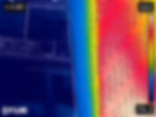
IMAGE: Test image from proof of concept. Image has been blurred to hide client identifying information. Note the distinguishable line between the glue (Red) and the backing material (Blue). The product (Yellow and green) is visible through the backing material as well.
As thermal
inspection cameras for industrial use are expensive and often come with
proprietary systems that are difficult to modify for prototyping, the Design Team
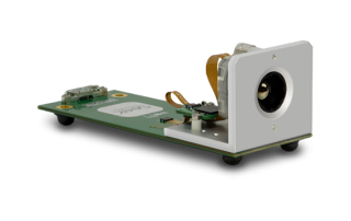
utilized a camera module supplied through a company called SEEK Thermal. This
package offered ease of modification, provided access to a supported Graphics
User Interface (GUI) in the form of an app, and was cost effective for a very
initial prototype. SEEK Thermal also included access to their developer portal
which provided additional information and programming flexibility. The camera
module was then attached to an adjustable magnetic mount, designed by the UTI
Design Team, that could be securely and noninvasively attached to the cast iron
frame of the machine that the process ran on. The camera fed its output, via a wired connection, to an inexpensive tablet
running SEEK Thermal’s app, downloaded from their developer portal, and was
mounted on an adjustable stand set up near the control panel for the machine.
The camera to tablet integration was simple to set up, taking less than an hour
of time. This setup allowed operators to not only determine the location of the
glue without interacting with the product, but also do so while adjusting the
glue application parameters in real time, reducing waste from their startup
calibration method. Overall, the prototype was installed and implemented for a
material cost of less than $1,500 dollars.
The Results & Benefits:
Once the camera system was implemented lineside, the operators immediately incorporated the Thermal /IR into the work flow. The output is intuitive to utilize and simplified the overall process rather than add additional complication. Though the resolution and framerate were lower, 320 x 240 and 27Hz respectively, the camera was clearly able to identify the glues edge. As a result, the system allowed the operators to complete their task without needing to get into the location and come into contact with the hazard. This meant the area could be fully guarded and accomplished the initial goal of the project.
The thermal camera also located potential process issues that previously went unnoticed. Through the cameras output of the thermal signature, a gradient was noticed across the web line. This identified a possible uneven application process. The phenomenon was noted by the client’s process engineer as providing an explanation for issues further down the line and provided an insight into how to fix them.
Since the prototype’s installation, the camera has also been used in other locations around the plant and has provided valuable information and additional design solutions by the owner. The use of a thermal camera has provided the client with information unable to be attained by the human eye. The next steps for this system are to make it more robust and integrate it directly with the owners control system using a higher quality SEEK Thermal camera. There has also been discussion about adding machine vision algorithms and integrating them directly into the controls, allowing the start-up of the system to be automated. Automation is something that the client does in-house however, so this would not be our responsibility should they choose to go that route. Were they to want to pursue additional support in setting this up, UTI would be able to facilitate design and implementation to the owners’ specifications. Recording the cameras feed for quality assurance and process information has also been discussed. This would allow our client to review the data on the discovery of a product defect and identify contributing process factors. While the camera itself would be unable to do that, the tablet that it is connected to could.
Estimated Application Costs & ROI:
The overall estimated application cost of this project was as follows:
- Hardware costs of the Seek Mosaic S316SPX Camera – $500
- 3D Printed Enclosure – $200 (Including design time)
- Mounting, brackets and power cable – $500est.
- Tablet and protective case – $300
- Installation – $500 est.
- Engineering – $12K (including evaluation and innovation development)
- The estimated TIC – less than $15k
The estimated ROI for this application:
- While the actual Owner’s cost saving are confidential, we were able to meet the following objectives:
- Nondestructive set up and alignment of the control system
- Eliminated the need for physical contact of materials as we now had real time in-line 100% inspection.
- Improved the product quality.
- While the actual Owner’s cost saving are confidential, we were able to meet the following objectives:
Conclusion: We estimated that the system had an ROI of less than 4 to 5 weeks.
What This Means:
UTI’s experience in novel thermal camera solutions has the potential to benefit numerous industries and processes in ways that may not be initially obvious. This highlights UTI’s ability to think outside the box and invent new and novel applications for groundbreaking technology in any industry. A few potential applications are:
- Quality control
- Maintenance, identifying leaky valves and worn-out wear parts
- Machine diagnostics, identifying hot spots like warm bearings and other potentially failing components
- Real-time production information, constant monitoring of temperature ranges
- Automated feedback and controls
- System set up & alignment, where visibility is limited by materials
- Improved safety in manufacturing by limiting human contact with hot materials or processes
Furthermore, the implementation of the prototype further showcases our ability to drive this innovation in a cost-effective manner that could potentially benefit you and your organization. Contact UTI today if you would like us to help you innovate and implement new solutions for your process.

Leave A Comment